IS-IS packet types
IS-IS calls PDU instead of packets.
- Hello packets: which are used for neighbor discovery and adjacency maintenance.
- Level 1 and level 2 link state packets (LSPs): which are used to transmit information about the topology of the network between intermediate systems.
- Complete sequence number packets (CSNPs): which are used to ensure the reliable flooding of LSPs across broadcast networks.
- summary of the IS-IS database.
- Partial sequence number packets (PSNPs): which are also used to ensure the reliable flooding of LSPs across broadcast networks. It has few purposes as mentioned below:
- Acknowledging that I have received LSP
- to request information. for example, I am missing a LSP in the database. how do you know about a missing LSP ? the answer is the CSNP. CSNP gives the summary of all the LSPs and its sequence numbers.
IS-IS Packet Encapsulation
IS-IS packets are encapsulated directly into data link layer, or layer 2, headers. that is: MAC header + ISIS Header + ISIS Data.
When an intermediate system wants to transmit data in a packet, it prepends an IS-IS header to the front of the data, and passes this entire block of data down to the data link layer to be transmitted as the payload of a packet. Rather than allowing the data link layer to determine the destination physical address using the address resolution protocol (ARP) cache, IS-IS passes one of several physical addresses to the data link layer software to use as the destination.
The layer 2 multicast which are used to transit packets:
- Packets transmitted to all level 1 intermediate systems are sent to the layer 2 address 01-80-C2-00-00-14.
- Packets transmitted to all level 2 intermediate systems are sent to the layer 2 address 01-80-C2-00-00-15.
- Packets which need to be transmitted to all intermediate systems, whether they are level 1 or level 2 intermediate systems, are sent to the layer 2 address 09-00-2B-00-00-05.
- Packets which need to be transmitted to all end systems are transmitted to the layer 2 address 09-00-2B-00-00-04
Type-Length-Value (TLV) Data Structures
IS-IS carries all the payload in the Type, length, values format(TLV). All these different kind of payloads – everything from information about an intermediate system’s existence to what links and neighbors it is attached to – has a common packer header.
Below is the format of the common ISIS header:
In above,
ID Length
A one-octet field which indicates the length of the system identifiers in the network. A 0 in this field indicates system IDs will be six bytes long; any other number indicates the number of bytes in the system ID. While in theory intermediate systems can have an identifier of any length, in reality no implementation of IS-IS has ever accommodated variable length system identifiers. Instead, an identifier of six octets (bytes) is assumed.
IS-IS LEVEL and adjacency BRIEF
In IS-IS, it’s like this:
[Level 1]—-[Level 2]—-[Level 1]
You have a Level 2 backbone, and then optionally you have any number of Level 1 routing domains that connect to it. The Level 2 backbone network only knows the Level 2 topology, and each Level 1 network only knows its own topology.
You then have “Level 1/Level 2” routers, or “L1/2″ for short”, which act exactly like OSPF Area Border Routers: they take addresses from Level 1, and re-advertise them into Level 2. They also know the topology of both levels. As the name suggests, L1/L2 routers connect an L1 non-backbone to the L2 backbone.
By default, the L1/L2 router takes all the IPs in Level 1, and advertises them up to the Level 2 backbone. This makes sense, for full reachability.
However, by default, the L1/L2 routers does NOT advertise things from Level 2 down to Level 1. Instead, you just advertise a default route, and you create a policy to leak anything extra.
a link a can be part of both a Level 1 topology, and the Level 2 backbone, at the same time!
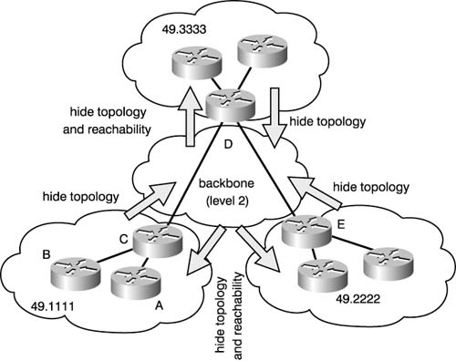
Below is an example:
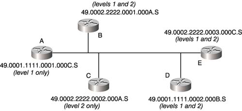
- Intermediate system A, since it is configured to accept only level 1 adjacencies, will build an adjacency only with D. It cannot build an adjacency with B, C, or E because these intermediate systems are in different areas.
- Intermediate system B will build a level 2 adjacency with C, since they are both configured to build level 2 adjacencies, even though they are in the same area (only level 2 routing information will be exchanged over this adjacency).
- Intermediate system B will also build a level 2 adjacency with D, since they are in different areas and both are configured to accept level 2 adjacencies. Intermediate systems B and D will not build a level 1 adjacency, since they are in different areas.
- Intermediate system B will build both a level 1 and level 2 adjacency with E, since they are both configured to accept both adjacency types and they are both in the same area.
- Intermediate system C will build level 2 adjacencies with B, D, and E.
- Intermediate system D will build a level 1 adjacency with A, and level 2 adjacencies with B, C, and E.
- Intermediate system E will build a level 1 adjacency with B, and level 2 adjacencies with B, C, and D.
Neighbor Discovery(Hello)
When an intermediate system is first attached to a link (or physical interface, either through the booting process, configuration, or bringing the link up), it will begin sending hello packets, which discover and maintain neighbor adjacencies. If it receives hello packets back from any other IS, it will begin building an adjacency with this new neighbor.
- On point-to-point links, a three-way handshake is used to establish a reliable adjacency between the two end points.
- On broadcast networks, the local MAC (physical layer) address of the IS must be in the hello packets received from other intermediate systems for a neighbor relationship to be formed.
Hello packet format in Broadcast:
Database Exchange
To exchange databases, four special types of packets are used: level 1 and level 2 link state packets, complete sequence number packets (CSNPs), and partial sequence number packets (PSNPs). Each of these packet types is described below.
Level 1 and Level 2 Link State Packets
In addition to the information contained in the common IS-IS packet header,level 1 and level 2 link state packets include the fixed fields as shown below as well as variable length fields encoded as TLVs.
DOMAINS IN IS-IS
First of all, what is a domain? A domain is a logically contiguous group of intermediate systems which all have the same set of topology information, or link state packets. All the intermediate systems within a domain share a common view of the world.
Why we need these domains ? : so that we can flood only within that domain.
What are the domains in IS-IS
IS-IS provides the means to create logical flooding boundaries by breaking the network into one level 2 routing domain and multiple level 1 routing domains.
A domain is a group of intermediate systems, generally within a single geographical region, that is an identifiable section of the network.
.The intermediate system that sits on the level 1/level 2 border doesn’t simply forward the LSPs it receives from the level 1 intermediate systems; it determines the reachable destinations advertised in the level 1 LSPs and includes them in a level 2 LSP for advertisement to its level 2 peers.
NSAP/NET addressing
- IS-IS uses connectionless network protocol(CLNP) addresses
- When we assign a CLNP address to a router, it is called a Network Service access point(NSAP) address. it is also called NET address in Cisco/arista.
- Only one address is needed per router, not per interface
- NET addresses can be 20 bytes long
- NET address are in Hexadecimal(1 Hex has 4 bits. 2 Hex makes 1 byte)
Addressing:
49 + Area ID(variable bytes) + system-id(6 bytes) + 00
Example:
49.0001.1111.1111.1111.00
In above example(we should always read from right to left):
49 means private ISO address.
0001 is the area
1111.1111.1111 is the system ID
00: it is always zero zero
HOW IS-IS forward packets:
- A router check’s packet destination. Now, this destination in NOT the IP destination, It is OSI routing domain based address destination.
- All the router will build OSI routing table
- Level 2 routers will be level 2 OSI routing table for different areas. keep in mind, level 2 router in different areas can talk to each other.
- A router will check packet destination based on the OSI routing table:
- If it is different area, routed based on the area address
- if it is same area, routed based on the system id
- If you are a level 1 router:
- inter-area packets are sent to the closest L1/L2 router
- L1/L2 router sets the “attached” bit
- intra-area packets are routed based on the L1 database
- inter-area packets are sent to the closest L1/L2 router
- if you are a level 2 router:
- inter-area packets are routed based on the L2 database
- if you are level1/level2 router:
- inter-area packets are routed based on the L2 database
- intra-area packets are routed based on the L1 database
- set the “attach” bit while advertising L2 routes to L1. This tells L1 router that level1/level2 router is the candidate to receive default.